Product Description
| Main technical parameter |
| Items. |
INNER VESSEL |
JACKET |
| MATERIAL |
Stailess steel 304/316,Carbon Steel |
Stailess steel 304/316 |
| DESIGN PRESSURE(Mpa) |
Customized |
Customized |
| DESIGN TEMPERATURE(ºC) |
-196~800ºC |
-196~800ºC |
| WORKING TEMPERATURE(ºC) |
-196~700ºC |
1,The basic structure and characteristics of reactor: the Stainless Steel reactor is composed of tank body, cover, agitator, jacket,driving system, shaft seal. Material and the nozzles are opened for customization.
2,Stainless steel reactor heating methods include electrical heating, oil heating, gas heating, water heating (or cooling), and flame heating.
3,Jacket types are : ordinary jacket, outer spiral pipes jacket, and oil heating jacket. All these types are equipped with diversion devices.
4,The stirring forms generally cover: blade type, anchor type, frame type, spiral rod type, scraper type, etc. High-speed types include dispersed impeller type, turbine type, high shear type and thruster type. Customers can choose 1 from above mentioned type accordingly.
5,The driving system include ordinary motors, flame-proof motors, frequency flame-proof motors, etc. The reducers include cycloidal pinwheel type and helical gear box type. Types of shaft seal are stuffing seal, mechanical seal,magnetic seal. The bottom outlet forms include ball valve and stainless steel valve.
·Products can be customized to meet customers’ needs in the aspects of structural design, function, capacity, and various working conditions ,etc.
·A series of examinations will be taken before the final fabrication of the product are ready to put into batch production, inspection can be made any time before the final fabrication is ready.
·We will provide instant service from the design drawings to after sales constantly CZPT the feedback from users.
·The desgin department provide professional drawings for evaluating feasibility and practicability in the perspective of users.
ZheJiang CZPT was established in 1998 and is located in HangZhou, the hometown of glass CZPT in China. It is a CZPT chemical equipment manufacturer in northern China, specializing in the production of glass-lined reactors, stainless steel reactors, carbon steel reactors and PTFE sparied, PP lining, alloy composite reactor, agitator, storage tank, heat exchanger, shell and tube condenser, tower, film evaporator, vacuum rotary dryer, high pressure laboratory reactor, full-set chemical automatic equipment .The products produced by our company are supplied to the whole country and dozens of countries around the world , and are widely used in petroleum, chemical, pharmaceutical, dye, mining and metallurgy and other fields. The supply objects include enterprises (Qilu Pharmaceuticals, China Wanda, etc.), scientific research institutes (HangZhou Research Institute of Chinese Academy of Sciences, China Sinochem Research Institute, etc.), institutions of higher learning (HangZhou Institute of Technology, HangZhou Maritime University, etc.), etc.
PTFE Lined Storage Tank Plastic Lined Storage Tank Heat Exchanger Double Cone Vacuum Dryer
Stainless SteelStorage Tank glass lined reactor Column Vertical Storage Tank
FAQ
Q1: Are you a factory or a trading company?
A1: CZPT Heavy Industry Group Co., Ltd. is an integrated industry and trade enterprise with 7 subsidiaries under its
jurisdiction. It has the business capabilities of design, manufacturing, trade integration, and independent import and export.
Q2: Will there be any guarantee if I buy from you?
A2: We promise to provide a one-year warranty (from the date of delivery) for all products we currently sell.
Q3: Do you provide installation guidance or other after-sales service?
A3: Yes, of course. Installation drawings and installation manuals are provided. If you are still unable to assemble, we will
arrange for our engineers to help you with voice or video contact.
Q4: What are the payment methods and terms you accept?
A4: The payment methods we accept include: T/T, L/C, D/P; after signing the contract, the customer needs to pay 30% of the deposit first, and the remaining 70% of the payment is completed in the delivery money.
Q5: What is your delivery time?
A5: We can arrange FOB, CIF shipping methods. Usually, the delivery time for 1 device is 45 to 50 days, depending on the shipping method.
Q6: How do you pack and ship the equipment?
A6: We offer sea, rail or combined transportation. At the same time, we also provide LCL (LCL), Full Container (FCL), Flat Rack (FR), Bulk and Express to ensure that the goods are safe and free from damage.
| After-sales Service: |
1 Year Free Parts |
| Warranty: |
1 Year |
| Function: |
Storage Pressure Vessel, Separation Pressure Vessel, Heat Pressure Vessel, Reaction Pressure Vessel |
| Application: |
Mixture |
| Material: |
Stainless Steel |
| Pressure: |
0.1MPa≤p<1.6MPa |
| Samples: |
US$ 1000/Piece
1 Piece(Min.Order)
|
Request Sample
|
| Customization: |
Available
|
Customized Request
|

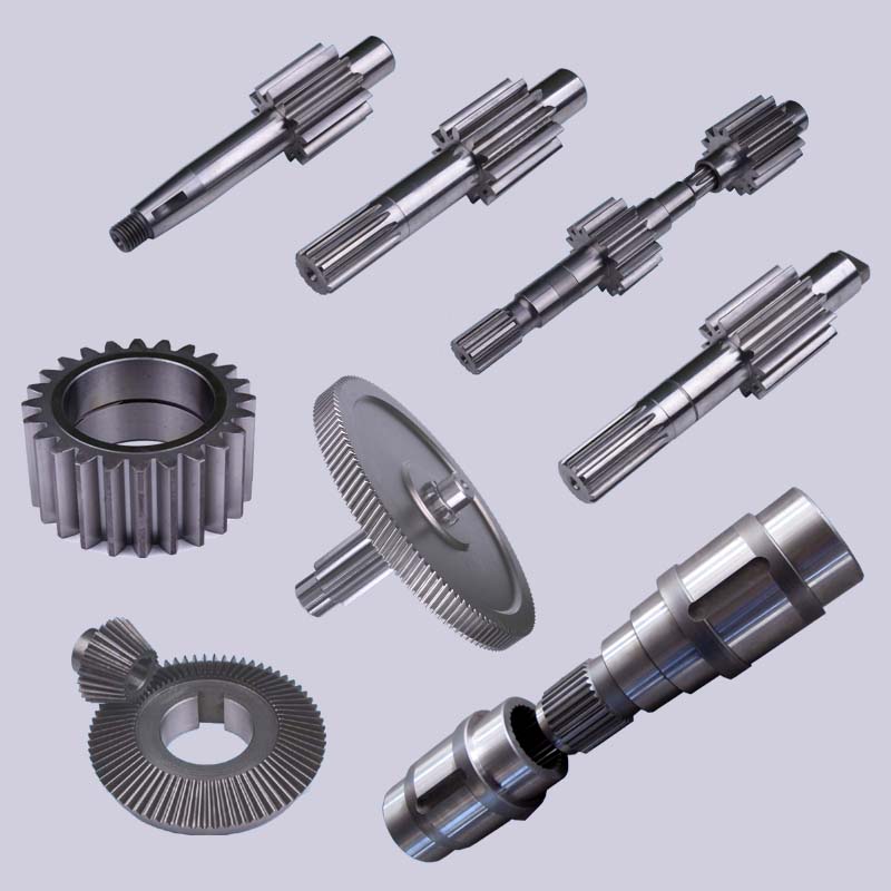
The Basics of a Cyclone Gearbox
Besides being compact, cycloidal speed reducers also offer low backlash and high ratios. Because of the small size of the drive, they are ideal for applications where space is a problem.
Involute gear tooth profile
Almost all gears use an involute gear tooth profile. This profile has a single curve, which means that the gear teeth do not have to be aligned closely with each other. This profile is smooth and can be manufactured easily.
Cycloid gears have a combination of epicycloid and hypocycloid curves. This makes them stronger than involute gear teeth. However, they can be more expensive to manufacture. They also have larger reduction ratios. They transmit more power than involute gears. Cycloid gears can be found in clocks.
When designing a gear, you need to consider several factors. Some of these include the number of teeth, the tooth angle and the lubrication type. Having a gear tooth that is not perfectly aligned can result in transmission error, noise and vibration.
The tooth profile of an involute gear is usually considered the best. Because of this, it is used in a wide variety of gears. Some of the most common applications for this profile are power transmission gears. However, this profile is not the best for every application.
Cycloid gears require more complex manufacturing processes than involute gear teeth. This can cause a larger tooth cost. Cycloid gears are used for less noisy applications.
Cycloid gears also transmit more power than involute gears. This can cause problems if the radii change tangentially. However, the shape is more simple than involute gears. Involute gears can handle centre sifts better.
Cycloid gears are less susceptible to transmission error. Cycloid gears have a convex surface, which makes them stronger than involute teeth. Cycloid gears also have a larger reduction ratio than involute gears. Cycloid teeth do not interfere with the mating teeth. However, they have a smaller number of teeth than involute teeth.
Rotation on the inside of the reference pitch circle of the pins
Whether a cycloidal gearbox is designed for stationary or rotating applications, the fundamental law of gearing must be observed: The ratio of angular velocities must be constant. This requires the rotation on the inside of the reference pitch circle of the pins to be constant. This is achieved through a series of cycloidal teeth, which act like tiny levers to transmit motion.
A cycloidal disc has N lobes which are rotated by three lobes per rotation around N pins. The number of lobes on a cycloidal disc is a significant factor in determining the transmission ratio.
A cycloidal disc is driven by an eccentric input shaft which is mounted to an eccentric bearing within an output shaft. As the input shaft rotates, the cycloidal disc moves around the pins of the pin disc.
The drive pin rotates at a 40 deg angle while the cycloidal disc rotates on the inside of the reference pitch circle of pins. As the drive pin rotates, it will slow the output motion. This means that the output shaft will complete only three revolutions with the input shaft, as opposed to nine revolutions with the input shaft.
The number of teeth on a cycloidal disc must be small compared to the number of surrounding pins. The disc must also be constructed with an eccentric radius. This will determine the size of the hole which will be required for the pin to fit between the pins.
When the input shaft is turned, the cycloidal disc will rotate on the inside of the reference pitch circle of roller pins. This will then transmit motion to the output shaft. The output shaft is supported by two bearings in an output housing. This design has low wear and torsional stiffness.
Transmission ratio
Choosing the right transmission ratio of cycloidal gearbox isn’t always easy. You might need to know the size of your gearbox before you can make an educated choice. You may also need to refer to the product catalog for guidance. For example, CZPT gearboxes have some unique ratios.
A cycloidal gear reducer is a compact and high-speed torque transmission device that reverses the direction of angular movement of the follower shaft. It consists of an eccentric cam positioned inside a cycloidal disc. Pin rollers on the follower shaft fit into matching holes in the cycloidal disc. In the process, the pins slide around the holes, in response to wobbling motion. The cycloidal disc is also capable of engaging the internal teeth of a ring-gear housing.
A cycloidal gear reducer can be used in a wide variety of applications, including industrial automation, robotics and power transmissions on boats and cranes. A cycloidal gear reducer is ideally suited for heavy duty applications with large payloads. They require specialized manufacturing processes, and are often used in equipment with precise output and high efficiency.
The cycloidal gear reducer is a relatively simple structure, but it does require some special tools. Cycloid gear reducers are also used to transmit torque, which is one of the reasons they are so popular in automation. Using a cycloidal gear reducer is a good choice for applications that require higher efficiency and lower backlash. It is also a good choice for applications where size is a concern. Cycloid gears are also a good choice for applications where high speed and high torque are required.
The transmission ratio of cycloidal gearbox is probably the most important function of a gearbox. You need to know the size of your gearbox and the type of gears it contains in order to make the right choice.
Vibration reduction
Considering the unique dynamics of a cycloidal gearbox, vibration reduction measures are required for a smooth operation. These measures can also help with the detection of faults.
A cycloidal gearbox is a gearbox with an eccentric bearing that rotates the center of the gears. It shares torque load with five outer rollers at any given time. It can be applied in many applications. It is a relatively inexpensive asset. However, if it fails, it can have significant economic impacts.
A typical input/output gearbox consists of a ring plate and two cranks mounted on the input shaft. The ring plate rotates when the input shaft rotates. There are two bearings on the output shaft.
The ring plate is a major noise source because it is not balanced. The cycloidal gear also produces noise when it meshes with the ring plate. This noise is generated by structural resonance. Several studies have been performed to solve this problem.
However, there is not much documented work on the condition monitoring of cycloidal gearboxes. In this article, we will introduce modern techniques for vibration diagnostics.
A cycloidal gearbox with a reduced reduction ratio has higher induced stresses in the cycloidal disc. In this case, the size of the output hole is larger and more material is removed from the cycloidal disc. This increase in the disc’s stresses leads to higher vibration amplitudes.
The load distribution along the width of the gear is an important design criterion. Using different gear profiles can help to optimize the transmission of torque. The contact stress of the cycloidal disc can also be investigated.
To determine the amplitude of the noise, the frequency of the gear mesh is multiplied by the shaft rate. If the RPM is relatively stable, the frequency can be used as a measure of magnitude. However, this is only accurate at close to failure.
Comparison with planetary gearboxes
Several differences exist between cycloidal gearboxes and planetary gearboxes. They are related to gear geometry and manufacturing processes. Among them, there are:
– The output shaft of a cycloidal gearbox has a larger torque than the input shaft. The rotational speed of the output shaft is lower than the input shaft.
– The cycloid gear disc rotates at variable velocity, while the planetary gear has a fixed speed. Consequently, the cycloid disc and output flange transmission accuracy is lower than that of the planetary gears.
– The cycloidal gearbox has a larger gripping area than the planetary gear. This is an advantage of the cycloidal gearbox in that it can handle larger loads.
– The cycloid profile has a significant impact on the quality of contact meshing between the tooth surfaces. The width of the contact ellipses increases by 90%. This is a result of the elimination of undercuts of the lobes. In this way, the contact force on the cycloid disc is decreased significantly.
– The cycloid drive has lower backlash and high torsional stiffness. This allows a cycloidal drive to be more stable against shock loads. The cycloid drive is also a compact design, which is ideally suited for applications with large transmission ratios.
– The output hub of the cycloid gearbox has movable pins and rollers. These components are attached to the ring gear in the outer gearbox. The output shaft is also turned by the planet carrier. The output hub of the cycloid system is composed of two parts: the ring gear and the output flange.
– The input shaft of a cycloidal gearbox is connected to a servomotor. The input shaft is a cylindrical element that is fixed to the planet carrier.


editor by CX 2023-11-08
 because the most productive type of gearing answer, once the application of transmitting power and uniform rotary movement from 1 parallel shaft to one more is required. Established through the center distance, spur gears make a steady working speed drive. This drive velocity can be decreased or elevated by the variable quantity of teeth that exist from the driving gear.
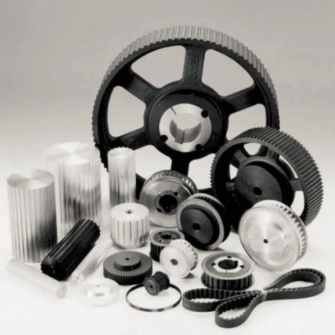 forms ( in line with type and width of belts). The materials used is cast iron EN-GJL-250 UNI EN 1561, and for only a few types it’s steel C45 E UNI EN 10083-1. They’ve a modest prebore that can be machined according to customers?¡¥ specifications. In addition essentially the most popular kinds can be found also with taperlock bore.
 a very good track record mainly because of our superior item top quality and after-sales service.


